Description
This project is a Microchip PIC microcontroller with an RS232 serial interface on one side and an I2C interface on the other. The I2C interface uses bit-banging on an 12F675 device.Important - All mention of RS232 on this page actually refers to RS232 waveforms operating at 5V TTL levels not +/-12V levels which would destroy the PIC device. An appropriate converter between the two must be used.
By sending commands on the RS232 interface it is possible to build up an I2C command in RAM in the PIC. After the final byte is sent on the RS232 interface the PIC will run through the stored sequence and send it out on the I2C interface, storing any data that has been read back. When the I2C command has finished the whole thing is copied back out of the RS232 interface.
The I2C command can be a sequence like:
START, write n bytes, STOP
or
START, write n bytes, RESTART, read m bytes, STOP
In addition to the generic command described above there are also some commands that will load, dump or erase an I2C EEPROM device. Each command starts by sending the size of the EEPROM (in bytes) and is finished by the PIC sending back an "OK" message. For the load command the data must also be sent and for the dump command the data is sent back. These commands are much quicker than using the generic commands above for each few bytes.
Pictures
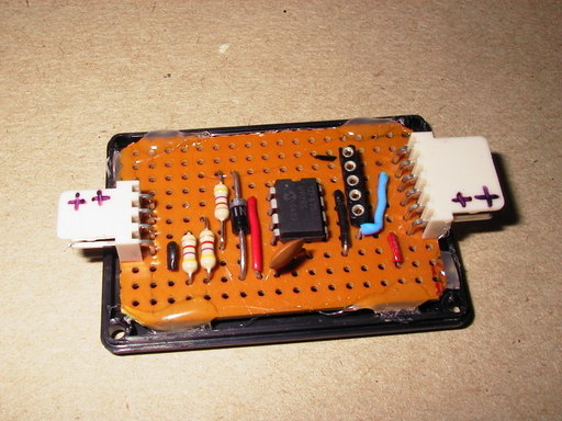
The circuit is built on stripboard with a DIL packaged IC and conventional through-hole passive components. The PCB is glued into the base of a small box for convenience.
The PIC microcontroller is the only IC and mounted approximately in the centre of the PCB. The RS232 connector is on the right with the I2C connector on the left.
PIC Software
The PIC software is written in assembler and this project was the development platform for the I2C library functions.The complete information for this project is available for download. This includes the library functions for the RS232 and I2C interfaces as well as the circuit diagram, layout diagram and various C programs. This project is included in the library of PIC code that is available for download.
Circuit Diagram
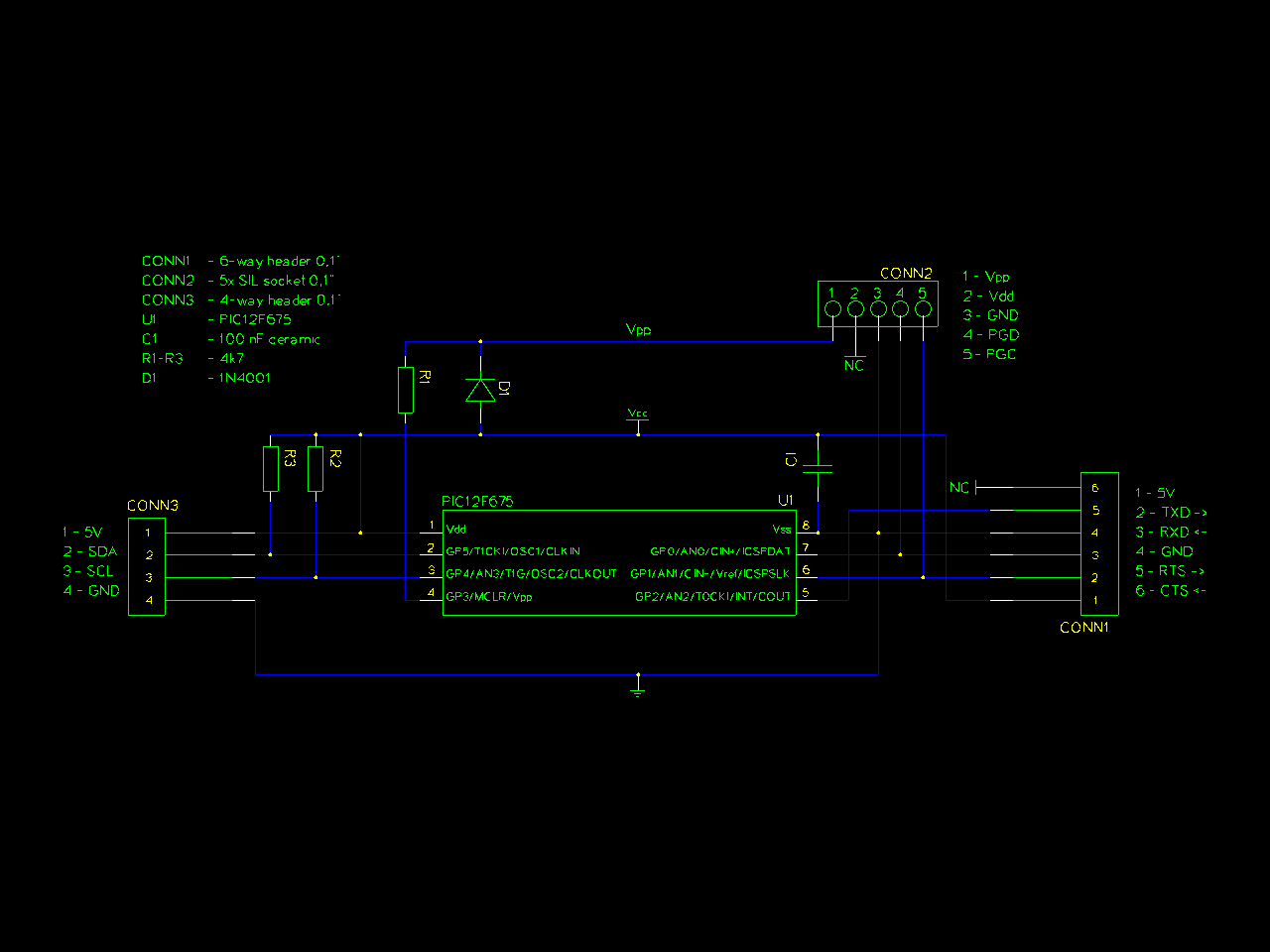
The circuit diagram is very simple with only the RS232 interface (a connector), I2C interface (2 pull-up resistors and connector), PIC (IC and decoupling capacitor) and ICSP (socket, 1 diode and 1 resistor).
Circuit Layout
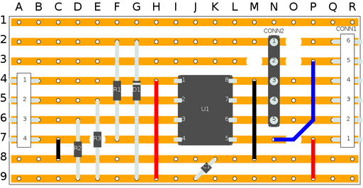
This simple PCB layout diagram shows the placement of the components on the stripboard. The view is from the top of the PCB, the same as in the photograph.